 The Leg Parts
As documented elsewhere, the main material is 56mm flat PVC ducting. This was run up a bandsaw twice to create two lengths of 54mm x 17mm U-section.
Annoyingly, when the duct was
 cut lengthways, the top edges of the section bent in towards one another. This is probably an effect of the way they are cooled in the factory. In order to make the opposite faces parallel, they were wedged apart with an appropriately sized piece of timber and a blowlamp applied to soften them.
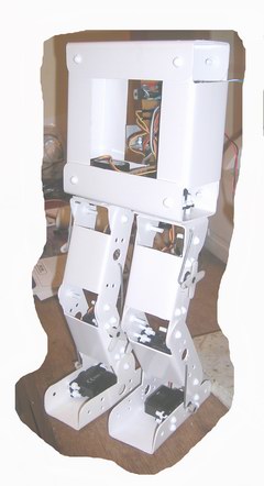
Every effort was made at the design stage (yes, there WAS a design stage) to make the components as similar and generic as possible. Each leg has two identical "leg pieces" (what an inventive name). They are short lengths of the U-section with cutouts at each end and the ends rounded so that they can rotate inside one another. There are holes drilled at the centre of the round edge and more holes for mounting the servos.
The servos are held in place by two
 means: there is a protrusion in the top which fits quite neatly into a 12mm hole and which takes most of the sideways force. The servos are prevented from rotating by four of the 4mm plastic rivets mentioned elsewhere.
The leg pieces have the drill pattern applied to both sides so that the servo can be mounted in either side (or if the design is rotated, the servo can be mounted "upside-down").
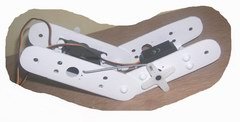
Crossed servo horns as seen here
 are used to control push-rods which move the leg parts relative to one another.
Hip Joints (Pelvis)
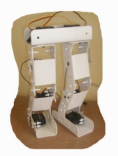
 Affording a second degree of freedom, these were more awkward than the ankle and knee joints. This time, the servos were mounted facing downwards from the "pelvis" of the robot. Holes are bored in the "top" of the hip joint and the servo head protrudes. The horn is mounted on the underside of the hip joint, to which it is secured with several small screws.
 Without this added degree of freedom, the robot would only be able to walk in a straight line. It is hoped that hip rotation will allow it to change direction. Here we see the "hips" from the underside. Only one leg is attached (the far one) and on the near side, we can see the servo head protruding.
Balancing Act
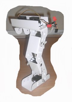
The robot will carry a power source (a 7.2V racing pack of the Tamiya type commonly found in radio-controlled cars). A square frame to house the battery will be constructed and attached to the pelvis in such a way that the battery can be moved from side to side. It is hoped that this mechanism will allow the robot to balance while one foot is off the ground.

No comments:
Post a Comment